Taking The Path Of Least Resistance
Using a Ram Tool
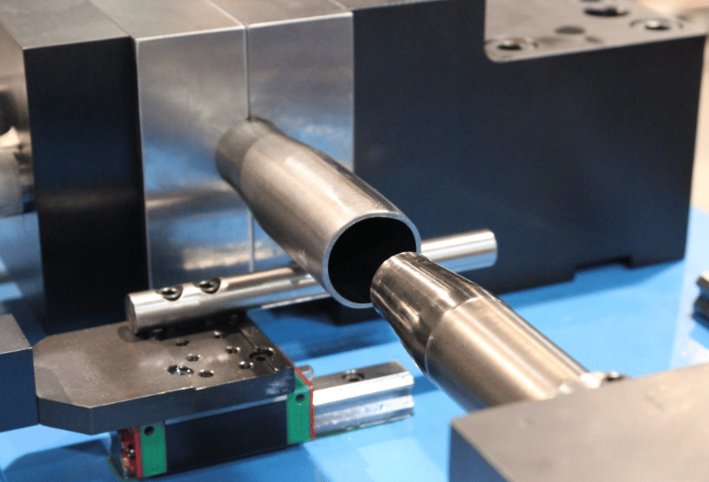
All events follow the path of least resistance…as to does the flow of metal. Take for example a simple welded steel tube. If you shove a ram tool in the end as seen in Photo 1, the tube will have a tendency to expand outward, providing it can withstand column loading and is clamped well. When the tube’s material is homogeneous, all behaves well and the outcome is a nicely expanded tube.
However, when the weld seam does not exhibit the same mechanical properties as the remainder of the tube’s cross section, the phrase “path of least resistance” may pop up. You see, when expanding a tube via a ram tool, the overall length of the blank becomes shorter as the tube is expanded. Therefore, if the blank length is 10” before expanding, then depending on how extreme the expansion is, the final tube length after expanding can be 9.25”. The length reduction of the blank is a function of, yet not limited to, the material, tube OD, wall thickness, length of expansion, and expanded OD.
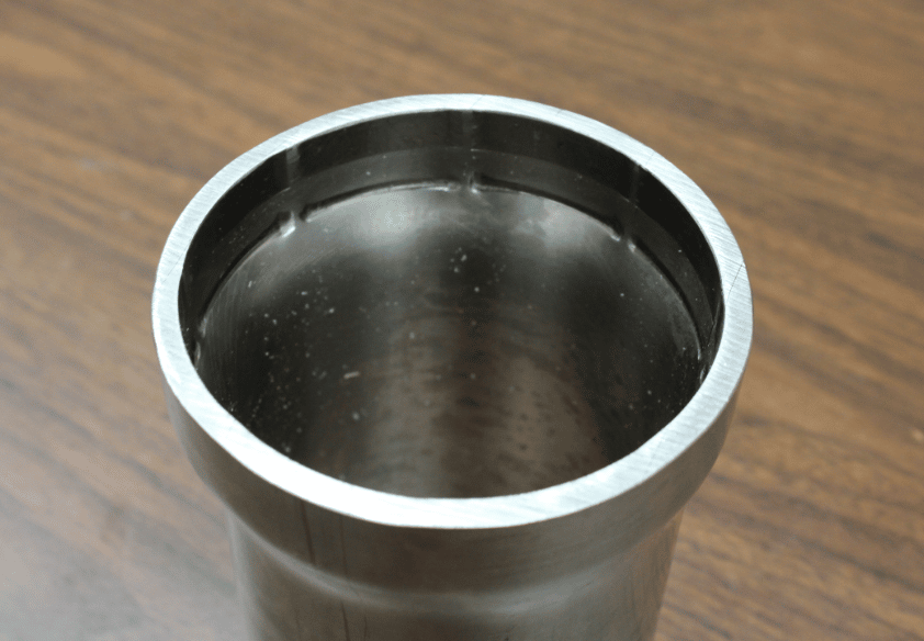
Now take a look at Photo 2. Here the face of the expanded tube is not flat. In fact, the area of the tube in the location of the weld seams protrudes outward. In other words, the weld seam, being harder than the rest of the tube, did not what to shrink or flow as much causing a protrusion to form on the tube’s face.
The process of forming metal is the process of least resistance. Weather it is bending or end forming, the tooling is there to guide the tube into a certain shape. With the right combination of tooling and the natural flow of metal, you often get the shape you are looking for.
Using Segmented Fingers
Now take a look at what happens when a different kind of tooling is matched up with the natural flow of metal. The tube in Photo 3 is a steel tube with a wall thickness that varies around the circumference by about .030”. That’s right…the .236” wall varies by about .030”.
The tool used to expand the tube was a set of segmented fingers. The segmented fingers did a fine job expanding the tube however, due to the nonsymmetrical wall thickness, the concentricity of the expanded end relative to the base tube itself increased as the expansion process was underway.
In this case, the thicker wall didn’t want to expand outward as easily as the thinner wall. The thicker wall offered increased resistance, causing the segmented fingers to concentrate on the weaker link of the thinner cross section. I should mention that in this case, the segmented fingers were allowed to float.
Good bad, or indifferent, you can always count on the natural flow of metal, and some folks, to take the path of least resistance.

George Winton, P.E. designs and builds CNC tube fabrication equipment for Winton Machine in Suwanee, GA. He can be reached at [email protected] or 888.321.1499.
About the Machines We Build
All of our semi-rigid coax and tube fabrication machines at Winton are designed, manufactured, and tested in-house. We have a large line of standard products as well as the ability to engineer the best solution for our customer’s needs. Our experienced sales staff makes sure that our customers can justify their capital equipment investment by offering a solution that is exactly what they need in order to manufacture their parts. Please contact us today to discuss your project.


