CNC Extrusion Bender – The Basics
Extrusions of all Sorts
Extrusions are everywhere. Just look at conveyor systems, scaffolding, playground equipment, swimming pools, and furniture. These are just a few industries that make use of extrusions that need bending. And let’s not forget about architectural windows or automotive window trim. We are surrounded by bent extrusions. Adding to the world of bent extrusions is bent rolled formed sections. Rolled formed sections, as well as extruded profiles, are bent everyday in production. The large radii bending is often a good match for either a roll bending process or a stretch bending process. The tighter radius bending often requires a rotary draw bending process.
Complexities of Extrusion Draw Bending
When the bend radius is relatively large, the compressive forces that an extrusion experiences are smaller when compared to the forces generated by a smaller bend radius. Therefore, as the bend radius becomes smaller, the compressive forces as seen by the extrusion become larger and thus the tooling requirements become more critical; critical to the point where thin cross sections of the extrusion want to buckle. It’s the design of the bend tooling that often becomes the deciding factor for success.
Managing the flow of an extrusion within the bend zone during the actual bending process is, in part, at the heart of making a good bend. Die clearances, die material, die hardness, and die surface finishes can all align to produce long-term quality bends.
Common Die Designs
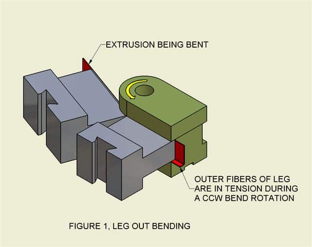
Take the simple case of an L profile with leg out bending, Figure 1. As the L profile is drawn in around the bend die, the outer section of the leg is in tension.
A finger type clamp and pressure die design could serve as the back stop in this application. In this case, bending is straight forward.
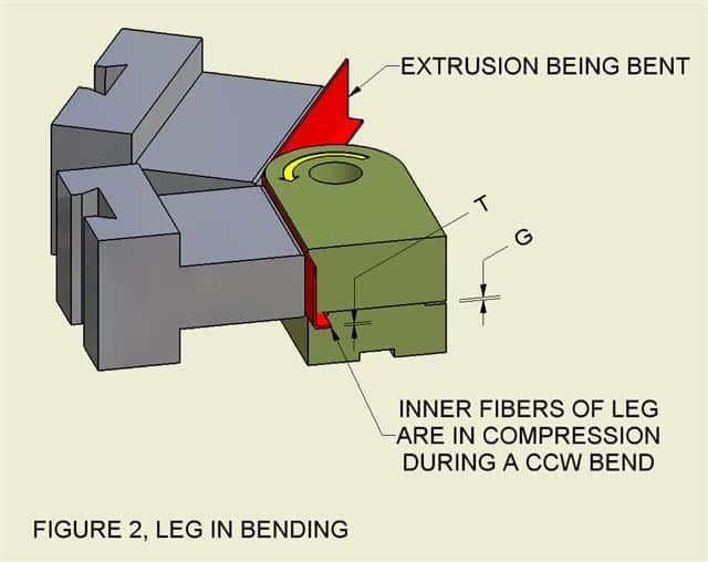
Now take the same cross section and turn the leg in; Figure 2. In this case the inner fibers of the leg are in compression and will have a tendency to buckle as the bend radius becomes smaller.
This is where managing the flow of the extrusion in the area of the bend itself can be critical for success.
Notice the gap G in the Figure 2. Too much clearance can lead to buckling of the extrusion. Too little clearance might prevent the extrusion from flowing into the bend die as the bend die rotates thru the bend. As the material thickness T becomes thinner, the tolerance on the gap G becomes more critical.
Even with the right gap G, the surface finish of the die can start to break down causing a galling effect as the extrusions attempts to flow into the thin mating section of the bend die. Needless to say, if the extrusion material is stainless steel, the surfaces of the bend die in contact with the extrusion itself must be able to with stand a fair amount of pressure. If not, the surface of the bend die will start to break down and thus influence the bend quality in a negative way.
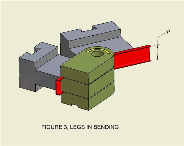
Now take the L channel in Figure 2 and add a leg. This forms a U channel. Bending the U channel with legs in highlights the importance of material growth during bending. From Figure 3, as the material rotates about the bend die, the overall height H of the extrusion will want to noticeably grow.
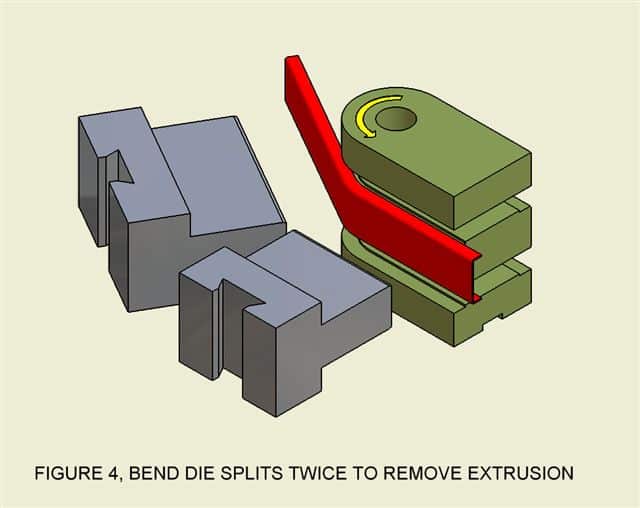
If the die design doesn’t accommodate this growth, getting the extrusion out of the die after bending can become difficult. One solution makes use of a split die actuator. A split die actuator maintains the geometric gaps during bending with the added bonus of the dies opening (splitting) after bending allowing for the removal of the extrusion itself. Figure 4 shows the U channel with legs in where the bend die is able to split above and below the channel itself. This provides a way for the extrusion to be released from the dies after bending.
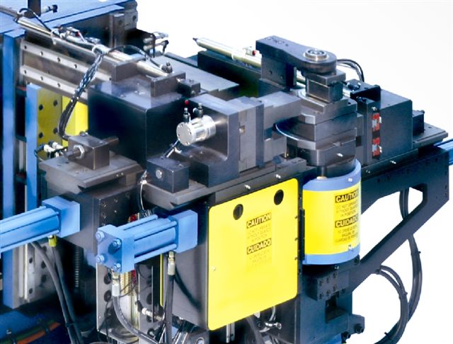
Some extrusions require more then one bend radius in a single part. This requires that the bender be setup more than once or a bender that supports more than one bend radius. Figure 5 shows a CNC extrusion bender that has a dual radius split die actuator.
The design of the tooling in this case allows for the bending of a U shaped channel legs out or legs in, large radius or small radius. This style of tool design can give an OEM maximum flexibility when it comes to designing bent extruded profiles into their products.
Material Handling – Post Bent Material
Some extrusions are long and thin with several bends. Sometimes the stiffness of an extrusion is unable to support the weight of the post bent material. In this case, as the part is processed thru a rotary draw bender, the post bent material exhibits the properties of a wet noodle and thus requires constant post bend support. Without this support, the post bent material can find it way into unwanted areas during the bending process.
Managing the post bent material can range from a simple static support to a microprocessor controlled material handling system that is integrated into the bender’s controller. It is application specific.
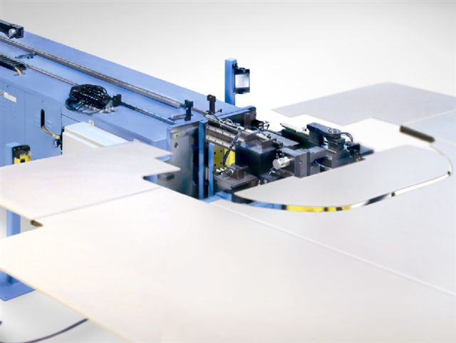
Figure 6 above shows a CNC extrusion bender that makes use of a microprocessor controlled material handling system used to support an extrusion during a bending operation. Notice the trap door towards the head of the bender. This door/support is programmable and is able to move up and down to facilitate the extrusion bending process. Without the trap door being programmable, the material handling of the extrusion in front of the bender would be a bear to manage.
Programming Extruded Profiles
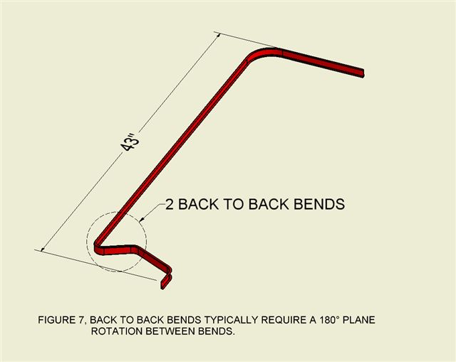
Programming a simple 1 or 2 bend extrusion doesn’t take a lot of time. However, programming multi-bent parts can often take time…more time then you would like. Nevertheless, there are modern software tools that can simplify the programming of a bent profile into an extrusion bender. Take the case of the profile show in Figure 7.
In this case the bent extrusion has several bends. Onc of the bends require a 180° plane rotation between bends. If you try to rotate the extrusion 180° between bends on a CNC bender, the extrusion itself might become limp and thus difficult to manage. This is not good for material handling. However, putting this profile on a right/left hand bender makes sense. This right/left hand bender eliminates the need to rotate the extrusion 180° between bends. The bend head on a right/left hand bender is able to bend both CW and CCW. This is very convenient for bending extrusions where the bends are not all in the same direction. However, by doing so doesn’t make the programming any easier.
This is where being able to read in the profile of the extrusion direct from CAD is a time saver. Importing a STEP file derived from a solid model will program the bender in under a second. After importing the LRA and centerline radius information, the next task for the software is to identify the CLR of a specific bend and be able place that bend in the correct stack providing the machine has at least a dual stack capability. The next task for the bender software is to be able to anticipate which bends are CW and which bends are CCW. After the software selects the stack position and bend rotation (CW or CCW), the next step would be to extrapolate the springback of the extruded material based on a library of predefined knowledge. Not to say the springback values will be exact, however, a projection can be made based on history.
After the bender’s software evaluates the above extrusion, the operator is left to select a standard tool package from a software library. A tool package might included the pressure die length, clamp die length, bend die information, material handling setup information, and various pressure settings.
When all said and done, 21st century bender software can really improve the time it takes to program an extruded profile.
Disadvantages
The initial cost to bring online the software tools for programming can be a limiting factor for some shops. Also, the having a machine on the floor that doesn’t make use of a dual stack feature can increase the time it takes to see a return on an investment.
A Window of Opportunity
Since 2010, people that bend extrusions have had to find additional ways to reduce the cost of goods sold. Without a means of doing so, production can easily move to a competitor. Gaining an edge and passing a portion of the savings along to your customer can go a long way towards a continued positive relationship.

George Winton, P.E. designs and builds CNC tube fabrication equipment for Winton Machine in Suwanee, GA. He can be reached at gwinton@wintonmachine.com or 888.321.1499.
Related Documents
About the Machines We Build
All of our semi-rigid coax and tube fabrication machines at Winton are designed, manufactured, and tested in-house. We have a large line of standard products as well as the ability to engineer the best solution for our customer’s needs. Our experienced sales staff makes sure that our customers can justify their capital equipment investment by offering a solution that is exactly what they need in order to manufacture their parts. Please contact us today to discuss your project.

