Understanding Vertical Compression Tube Benders
Manufacturers who bend tubing using the same process day in and day out are often searching for faster and more efficient tube bending machines that are capable of producing precision bent tubes. Daily applications range from aerospace to medical devices to children’s toys. Flexibility is often needed to form these parts when the bending process is the last step in an assembly process. Flexibility also includes quick die changes to accommodate different diameter tubing and constantly changing bend radii. A vertical compression bender fits the profile. Often used for dedicated applications, a vertical compression bender allows for the flexibility to change dies to accommodate different tube diameters and bend radii. By adding a few external stops, a vertical compression bender can quickly make several different bends on the same part in under 15 seconds.
Mechanics Of A Vertical Compression Bender
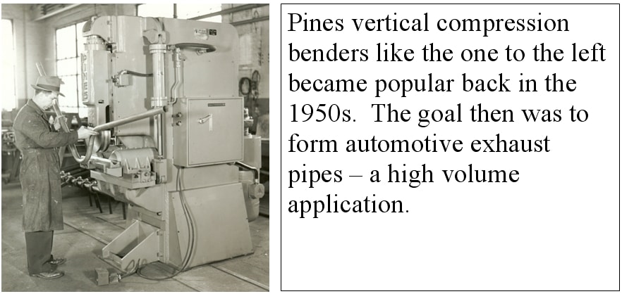
A vertical compression bender makes use of a bend die that advances through two wing dies. The drive system for the bend die is either hydraulic, pneumatic, or electrical. As the bend die advances downward toward the two wing dies, each wing die rotates outward and away from the advancing bend die. The wing dies support the tube along with the bend die in the area of the bend. The further downward the bend die advances the greater the bend angle is imposed on the part being bent. It is the job of the wing dies to hold the tube in position during the bending process. This is accomplished by an upward force on each of the wing die assemblies. A sufficient upward force (counter to the advancing bend die) is required to prevent the wing dies from separating from the bend die during the bending process. An upward force (often refereed to as the cushion) on the wing dies can be accomplished by an opposing cylinder to the bend die’s drive system. As the bend die advances through the wing dies the direction of the force from the cushion on the wing die assemblies changes. With this in mind, it is important to ensure adequate contact between the tube and the wing dies as all times. For large bend angles it may be necessary to increase the counter force to help prevent separation between the wing dies and the bend die. Each wing die is able to slides along a linear path away from its respective pivot point thus allowing a 1 to 1 contact between the tube and each wing die; see Figure 2. Properly adjusted, there should be no slip between either wing die and the tube itself. The 1 to 1 contact reduces friction and thus reduces the necessary force required by the bend die’s drive system. With 1 to 1 contact, crown tooling can be employed to reduce the ovality of the final bend. As the bend die retracts, springs return each wing die, along it linear path, to its home position.
Bend Die
The bend radius is typically machined to match the radius on the tube’s drawing. If the end user is particular about the actual size of the radius, it may be necessary to reduce the outside diameter of the bend die to compensate for a larger bend radius on the bent part itself. Remember, the larger the bend radius the greater the difference will be between the bend die radius and the actual radius on the part itself. The groove in the bend die is typically not a full radius. This detail provides for clearance between the bend die and the wing dies during the bending process. Die clearance from .003 to .010 for small diameter tubing is a good starting point. Without clearance the bend die would rub on the wing dies thus adding friction to the system. A-2 tool steel is commonly used for bend die construction. A-2 offers several advantages. It’s good to machine and it’s straight forward to heat treat. Check out your local dental supply house for a used heat treating oven that goes up to 2000°F. Quite often a dental supply house will have used heat treating ovens at a reasonable price. Small ovens work well for heat treating tube bending dies.
Wing Dies
The groove in the wing dies are usually a full radius machined to match the radius of the tube’s outside diameter. The length of the wing dies is typically eight time the tubes outside diameter. A-2 tool steel is a good choice for material selection. A Rockwell hardness of about C58 is desired for normal usage.
Understanding Bend Quality
Having dies that are machined to fit a particular size tube is an important step in keeping the ovality to a minimum. The size of the bend radius for compression bending will have an impact on the ovality. Too small of a bend radius can easily produce bends that look flat to the eye. Also, the amount of separation between the bend die and the wing dies during the bending process will greatly influence the final quality of the bend. Keeping the ovality to a minimum will require that the bender have plenty of stout. A stout machine is the first step in preventing die separation during the bending process. Without a strong foundation, the best dies will display excessive separation during the bending process. Ideally, the clearance between the bend die and wing dies should not grow during the bending process. When bending unequal length legs as seen by the wing dies, be careful to ensure that the die separation of just one wing die does not exist. Unequal leg lengths may produce unequal loads on the wing dies and thus can produce unequal die separation. Sufficient counter force on the wing dies throughout the bending process will help prevent this occurrence. Unequal lengths occurs when there is a short tube section in one wing die and a full tube length in the other.
Bend Angle Control
Todays production vertical compression benders employ everything from a manual screw stop to a microprocessor to control the bend angle. For manufacturers who make several setups per week on a compression bender may very well be interested in microprocessor controlled bend angle. For manufacturers who are bending the same part day in and day out may be able to forgo the liability of a computer and be quite content with a manual depth stop on the advancing bend die.
Disadvantages
The maximum bend angle to be achieved on most vertical benders is about 140 degrees(1). Anything more would prevent the wing dies form returning to their home position. Also, unlike a rotary draw bender, a vertical compression bender is not known for making several successive bends in one part.
Summary
Vertical Compression Benders work well in production environments. Most machines allow for the changing of dies to accommodate different bend radii and tube diameters. This makes a vertical compression bender flexible among numerous manufacturing tasks. For small diameter tubing, shop air is all that is needed to power these machines. Medical and automotive applications have been benefiting from the all pneumatic approach for decades.

George Winton, P.E. designs and builds CNC tube fabrication equipment for Winton Machine in Suwanee, GA. He can be reached at gwinton@wintonmachine.com or 888.321.1499.
About the Machines We Build
All of our semi-rigid coax and tube fabrication machines at Winton are designed, manufactured, and tested in-house. We have a large line of standard products as well as the ability to engineer the best solution for our customer’s needs. Our experienced sales staff makes sure that our customers can justify their capital equipment investment by offering a solution that is exactly what they need in order to manufacture their parts. Please contact us today to discuss your project.


